
 |
Bill Gustin recently presented a Webcast on standpipe operations,“Standpipe Operations Part 2: Water From The Outlet To The Nozzle.” Below are some answers to the questions listeners posed to him on the subject.
Q: No gloves [referring to a photo in one of the slides]?
A: A fair question that I am often asked during my presentations. We put on our gloves after we mask up. Our personnel are trained to don our PPE in the following sequence:
At no time do our personnel set their helmet or gloves down; they are trained to don their PPE while walking or climbing stairs. We have timed our personnel donning their SCBA mask, helmet, and hood with and without wearing gloves. We found that we get a better seal, cover exposed skin more carefully, and properly tighten the chinstrap in less time with gloves off (ultimately putting the gloves before operating) than attempting those functions while wearing bulky firefighting gloves.
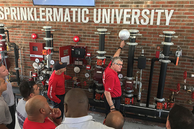
RELATED: Miami-Dade (FL) Fire Rescue Safety Stand Down, Part 1: Intro to Fire Suppression Systems | Part 2: Fire Pumps and Fire Trucks | Part 3: FDCs and PRVs | Part 4: Floor Control Valvies and Sprinkler Heads
Q: Many standpipe ops. trainers recommend always pumping into the FDC as opposed to letting the (building’s) fire pump do its job. It’s what our department does. But the FDC supply (piping) may be 3-inch (diameter) compared to a 5-inch supply (piping) Thoughts?
A: Your department is not wrong; there are many fire departments that pump the FDC as if the building’s fire pumps were not operating properly or were not there at all. As far as pipe diameter is concerned, it would have to be a small building not to have city supply piping to a standpipe system that is at least 6-inches in diameter. Remember, there can only be one source of water supplying a standpipe system; either the building’s fire pumps or the fire department pumper supplying the FDC; whichever one is pumping the highest pressure. As far as the diameter of pipe from the FDC and demand pressure for fire department pumpers, that should be posted at FDCs, must be calculated to include the fiction loss in the piping from the FDC to the check valve in the discharge piping of the building’s fire pump(s). If the pressure from the engine pumping the FDC is insufficient, then it will be pumping against a closed check valve, being held closed by the greater pressure developed by the building’s fire pump. Hence, the engine connected to the FDC will not be flowing any water. In this case it is very important to prevent the engine’s pump from overheating by flowing at least 100 GPM., such as through an open line lashed to an object. Additionally, there are systems where pumping the FDC at demand pressure is a necessity, not just a precaution, such as dry and manual wet standpipes.
Q: In a building with a fire pump supplying the standpipe, do you recommend using the fire pump or the FDC to supply the standpipe?
A: You have touched on a hotly debated issue. I say it depends on the building. For example, if you have buildings with fire pumps that are not regularly tested and poorly maintained, you better supply the FDC at system demand pressure. Additionally, say you have a fire of any significance in a fully sprinklered building; it begs the question, “Why didn’t the sprinklers control the fire?” Could it be that the building’s fire pumps failed to supply the sprinklers? Consider the possibility that you could have a company advancing a hoseline down a hallway that gets burned when they lose water because the building’s fire pumps suddenly fail. These are strong arguments in favor of pumping FDCs at system demand pressure as if the building had no fire pumps.
There are, however, valid reasons
why some departments connect to the FDC as a precaution but allow the building’s fire pumps to do their job. For example, say you have an extremely tall building with a high zone system demand of 500 PSI. Consider the inherent hazards of pumping an FDC at that pressure–hazards that can be avoided if the building’s fire pumps are adequately supplying the system. First, consider the pressure on the hoselines connected to the FDC. Therefore, many big city departments have special high-pressure hose specifically for pumping FDCs at high pressures. Additionally, the hoselines should be lashed to the FDC and pump discharges in case a section fails at a coupling. It is very important to keep the pump operator and civilians out of harm’s way by connecting to discharges on the opposite side of the pump panel and cordoning the area with traffic cones, scene tape, or barricades. Finally, as mentioned in a previous question, an apparatus pump supplying an FDC at high pressure will rapidly overheat to the point of self-destruction if it is not flowing sufficient water to keep it cool.
Now there are issues that are not open for debate: First, if your department lets the building’s fire pumps do the work they must still establish a water supply for an engine and connect hoselines from the engine to an FDC. Second; fire officers must not put blind faith in a building’s fire pumps. Remember, static pressure as read on an in-line gauge is meaningless. Don’t let head pressure in the standpipe or pressure maintained by the jockey pump fool you. Firefighters must fully flow the nozzle to check the in-line gauge and the quality of the stream before entering a hostile environment. As I advocated in my webcast, charge and flow the hoseline on the floor below the fire whether the fire floor hallway is “dirty” or not. If you have insufficient pressure and there are no kinks in the hoseline, you either have debris or a closed valve in the system, a defective or improperly set PRV, or the fire pumps are not operating properly. If the problem is fire pump failure, you are already connected to the FDC and ready to take over supplying the system.
Q: FDNY uses only 2 ½-inch with a 1 1/8 MST (smooth bore) tip for standpipe ops now. We are looking at 2-inch hose with a 1-inch tip as a lead length for residential HR fires only, not for taxpayer fires.
A: Are you sure about that? I could be wrong and, if so, will stand corrected but I believe that the FDNY is already using 2-inch hose with 2 ½-inch couplings with a 1-inch tip as their “leader length” on their 2 ½-inch hoseline at fires in compartmented residential high rises. It is my understanding that they specified 2 ½-inch couplings on their 2-inch hose to make it compatible with their 2 ½-inch hose without the need for adapters. Regardless, you are spot on with considering 2-inch hose. Suggestion: Try a 1 1/8-inch tip; we’re achieving a flow of 250 gpm through our 2-inch hose at 45 PSI nozzle pressure.
Q: We have always been taught to pump to the fire floor. However, with PRD/PRVs in place we must pump to the top most floor, correct?
A: Yes, you must pump to the roof level just to overcome the head pressure due to the height of a standpipe and that’s not considering nozzle pressure, friction loss in the system and hoseline, and overcoming the pressure developed by the building’s fire pumps. In terms of head pressure, say a 30-story building has a single-zone standpipe system and, for simplification, let’s assume that the roof level is 300 feet and the height of every floor is 10 feet. Multiplying 30 stories X 4.34 PSI elevation height per floor, rounded to 5 PSI/floor, would equal a head pressure of 150 PSI at the base of the standpipe; that’s 150 PSI exerted on check valves and back flow devices in the system. Your pumper supplying the FDC will not open those check valves unless it pumps over 150 PSI regardless of what floor the fire is on. Now, say the fire is on the fifth floor and we calculate 5 PSI/FL plus 100 PSI for the system and hoseline–that’s 125 PSI, insufficient pressure to overcome the head pressure acting on the clapper valves at the base of the standpipe and in the discharge piping of the building’s fire pump.
Q: Can you explain how the system pressure on the fire pumps work as it relates to pump discharge pressure to the FDC so we can overcome the check valve?
A: The best way to understand this is to first understand the requirements of National Fire Protection Association (NFPA) 14, Standard for the Installation of Standpipe and Hose Systems. NFPA 14 requires that standpipes in buildings constructed after 1993 can flow 500 gpm at 100 PSI from the two most hydraulically remote standpipe hose outlets on one standpipe riser and an additional 250 gpm at 100 PSI from any additional risers. Before a building can receive its certificate of occupancy, the fire pump and standpipe system must undergo an acceptance test to ensure that it meets the requirements of NFPA 14. For example, say a 30-story building has two standpipes; one in each stairwell. The authority having jurisdiction would witness a flow test that is typically conducted by flowing three roof manifold outlets; each outlet flowing 250 gpm at a minimum pressure of 100 PSI. Now say this building has one fire pump. The fire pump has no way of knowing what floor the fire is on it only knows ONE PRESSURE, that is, the pressure necessary to flow 750 gpm at 100 PSI at the roof. That pressure is calculated taking into account the following factors: 1) Friction loss in fire pump discharge and standpipe system piping, and; 2) Pressure loss due to elevation in the standpipe, in this case, at the very least, 30 floors X 4.34 PSI per floor. The fiction loss in pipe flowing 750 gpm can be quite significant, especially if the system is plumbed with several elbows. All factors considered, it would not be a surprise to find that this building’s fire pump can flow 750 gpm at a pressure of at least 300 PSI. It is very important to understand fire pumps are designed and tested on a pressure-volume curve; the greater the volume flowing, the lower the pump discharge pressure and, conversely, the less volume flowing, the greater the pressure. Therefore, if the building’s fire pump can develop 300 PSI while flowing 750 gpm, it will develop significantly higher pressures at flows less than 750 gpm. The highest pressure developed by a building’s fire pump is at churn, that is, with no water flowing except for the amount discharging from its relief valve, necessary to keep the pump from overheating. The system demand pressure, which should be posted at the building’s FDCs, is calculated by factors such as the building’s fire pump churn pressure and fiction loss in the piping between the FDCs and the discharge piping of the building’s pump. The bottom line is if the FDC is pumped at a pressure lower than the pressure developed by the building’s fire pump, it will fail to force open the check valve in the building pump’s discharge piping and will not flow any water into the system. Conversely, if the engine’s discharge pressure exceeds the pressure developed by the building’s fire pump, it will force open the check valve in the building’s fire pump and the engine becomes the sole source of water to the standpipe system. When this occurs, the building’s fire pump will churn, pumping against the check valve held closed by the greater pressure from the fire department pumper. To prevent overheating, a building’s fire pump at churn will flow a small amount of water from its casing relief valve.
Understanding the requirements of NFPA 14 will also help firefighters to understand the function and pressure requirements for pressure-reducing standpipe system hose outlet valves. In buildings constructed after 1993, NFPA 14 requires standpipe outlets to flow a minimum of 250 gpm at, as mentioned previously, a minimum pressure of 100 PSI. It is equally important to know that NFPA 14 requires that hose outlet pressures cannot exceed 175 PSI; hence, high pressures become problematic, especially on the lower floors of high-rise buildings. Again, consider our 30-story building; system pressure on lower floors would most likely exceed 300 PSI, hence PRVs are either factory set or adjusted in the field to limit the static and residual outlet pressure to 175 PSI. PRVs on lower floors are set or adjusted to reduce higher pressures than on upper floors and is based on the designed static and residual pressure on the inlet side of the valve. That begs the question, “What if the pressure on the inlet side of the PRV is below the design pressure?” The chilling answer is that the pressure will be insufficient to open the floating valve inside the PRV to provide an adequate flow. We have many government-subsidized public housing buildings in my company’s district. One 12-story building has PRVs on the first eight floors and conventional outlets on the upper four floors because the elevation reduces the system pressure to below 175 PSI. A system demand pressure of 205 PSI is clearly posted at each FDC. We intentionally under pumped the FDC at 150 PSI, which is our department’s standard starting pressure for standpipe systems, and flowed the first-floor hose outlet. The result? A flow no greater than a garden hose! Like a building’s fire pump, PRVs don’t know what floor the fire is on.
Q: Do we need to have one person at the (outlet) valves to act as an operator?
A:Yes. In an ideal world, one firefighter would remain at the outlet with his eyes fixated on the in-line gauge, ready to adjust the pressure if necessary. I can’t spare a firefighter to exclusively monitor the pressure, so I rely on a first-floor mule who pushes the hoseline up the stairs to check the pressure as often as he can. Again, this is another reason why I like to charge the hoseline and fully flow it to adjust the pressure on the floor below the fire, whether the fire floor is dirty or not. I want the firefighter opening the outlet valve and the nozzle firefighter to be talking to each other and agree on the pressure before we snake the line up the stairs
Q: What’s your opinion on using an (1 ½ X 2 ½-inch) increaser to support 2 ½-inch lines off a class II outlet?
A:In an ideal world, a firefighter would never use class II outlets because they were intended for occupant use only, but firefighters do not operate in an ideal world. I’m sure that you are aware of cases where ladder company members without a hoseline have successfully stopped auto extension to upper floors by stretching a “house line” from a cabinet. Ideal? No. Expedient? Yes. To be clear, I am not advocating the use of class II outlets. There is, however, one exception: Say you have a smoky fire in a linen storage area of a hospital. Use your increaser to connect your 2 ½-inch hose to a 1 ½-inch class II outlet between smoke barrier doors to limit the spread of smoke. I say the gain of not having to relocate a lot of patients is worth the risk. If you choose this operation, you must realize that the class II outlet will flow a very limited amount of water, so it is very important to have a company with a charged hoseline connected to a class I or class III outlet standing by outside the smoke barrier doors.
Q: Any perceived pitfalls of using 100-foot lengths of 2-inch (hose) in place of 50-foot lengths? Fewer connections to make. Also, do you have a benchmark for hose you want to see to the fire compartment door before the nozzle team makes entry?
A:
The only pitfall I can see is a firefighter who was in trouble and had to follow the hoseline to safety would have to travel farther to find a coupling to determine if he was headed towards the stairwell or to the nozzle. I don’t know if they are still on the market but I’ve seen rubber rings with large raised directional arrows that can be placed on hose. A nozzle’s stream can every part of the average size apartment with 50 feet of hose, therefore, if the door to the fire apartment is closed, keeping the public hallway relatively clear, pull up 50 feet of hose to the apartment door before making entry. Accordingly, it is very important to clearly mark the middle of 100-foot lengths.
Q: Do you know of a good, hands on school focusing on high-rise for experienced fire personnel?
A:Any class instructed by Ray McCormack or Dave McGrail would be excellent.
Q: Why install an in-line pressure gauge after the gated wye? It is not going to tell you if there are kinks before or after the appliance. It seems like there is an excess of equipment here.
A: I’m no fan of using a wye for standpipe ops other than to extend a hoseline as I explained in the webcast. It is very important to know that NFPA 14 requires a minimum flow of 250 gpm per outlet. Anything more than 250 gpm is a gift unless you have flow tested the building. If you do charge a second hoseline from a gated wye, you must have in-line gauges connected to both outlets and the first line must be flowing to ensure that you are not stealing water from it when you charge the second line. I examine the complications of using a wye in my article entitled “Operating More Than One Hoseline from A Standpipe” in the May 2015 edition of Fire Engineering.
Q: How can we determine correct system pressure?
A:The ideal way would be to shut the building’s fire pumps off, connect hoselines to roof manifolds or top floor outlets and pump the FDC. My department does this as part of the standpipe flow test before a new building is occupied. I fully realize that this is seldom possible with existing buildings. Other ways to determine the demand pressure is to examine the building’s plans for its sprinkler and standpipe system and records of previous fire pump and flow tests. Additionally, look at the fire pump’s speciation plate which will indicate its churn or highest pressure. Keep in mind that you may have to pump the FDC at higher than churn pressure to compensate for friction loss in the piping between the FDC and the discharge piping of the pump. Regardless of how you determine the demand pressure, you must verify it by charging and flowing the hoseline on the floor below the fire.
Standpipe Operations Part 2: https://www.fireengineering.com/webcasts/2017/11/standpipe-operations-part-2.html
Bill Gustin Q & A: https://www.fireengineering.com/articles/2018/01/standpipe-operations-q.html
With Capt Bill Gustin, Miami Dade Fire Rescue Double Tree Milwaukee City Center Milwaukee, Wisconsin
With Capt Bill Gustin, Miami Dade Fire Rescue Double Tree Milwaukee City Center Milwaukee, Wisconsin